Research theme 05
Coherence in the absorbed energy: how a rough surface organizes light into a pattern
Laser-induced periodic surface structures are not written by the beam profile. They are written by the interference between the incident light and the light that the surface itself scatters. Solving Maxwell equations on a real, disordered surface makes that statement quantitative, and shows which part of the scattered field is responsible for which family of structures.
Finite-difference time-domain modelling of light absorption below rough surfaces. With Vladimir Yu. Fedorov, Anton Rudenko, Hao Zhang, Razvan Stoian and Stefan Witte.
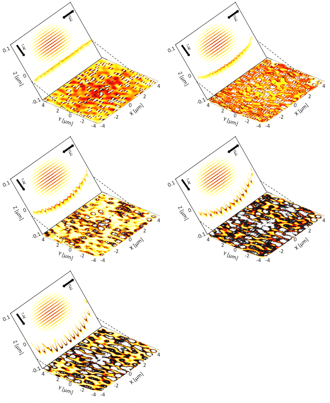
01Interference, not resonance
Below the surface the total field is the sum of the refracted wave and the wave scattered by the roughness. The absorbed energy is proportional to the squared modulus of that sum, and since the scattered amplitude is small compared with the incident one, the cross term dominates: the modulation is an interference term, linear in the scattered field, not a resonance. This is the reason a nanometric defect can imprint a micrometric pattern.
The idea goes back to the efficacy-factor theory of Sipe and co-workers, who derived the asymptotic form of the field scattered at infinite distance by a confined region of surface roughness, including both a surface plasmon contribution and radiative remnants. Solving Maxwell equations numerically keeps that structure but removes the asymptotic assumptions, so the near-field region, where most of the subwavelength physics happens, is described as well.

The two curl equations advanced on a staggered grid. The dispersive metal enters through the displacement field, a Drude permittivity giving n = 3.02 + 3.51i at 1.03 µm and a 23 nm skin depth.

Energy absorbed per unit surface, from the squared field integrated over time and over depth. The areas that absorb most are the ones later extruded, and they seed the growth of the periodic structures.
From the field history at every grid point the absorbed energy follows directly: the power delivered per unit volume is the scalar product of the field with the current, which for a Drude metal reduces to an expression involving only the real and imaginary parts of the index. Integrating over time and depth gives the map that seeds the relief.
02Near field or far field?
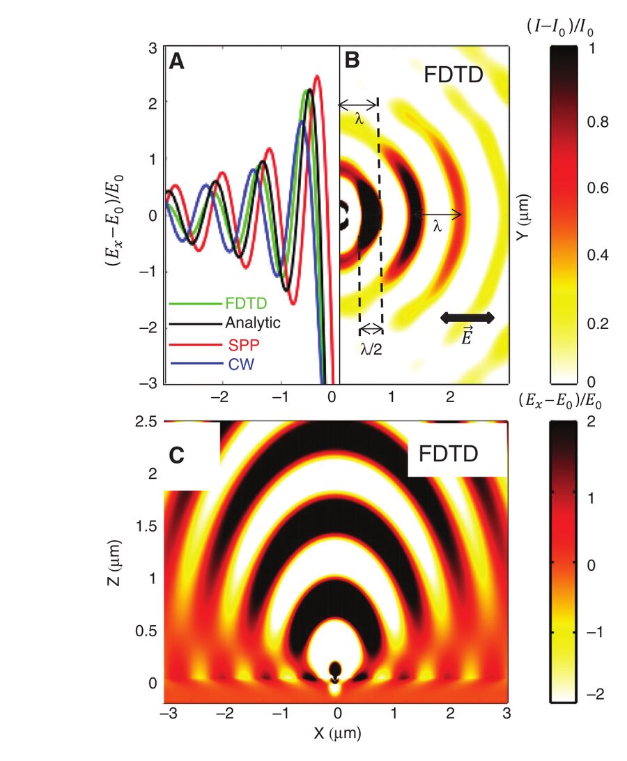
The cleanest way to see where the periods come from is to reduce the surface to a single subwavelength scatterer and to solve its response exactly. Two surface waves leave the defect. The surface plasmon polariton carries a wave vector fixed by the permittivity of the metal and decays exponentially. The quasi-cylindrical wave is a superposition of evanescent components with no fixed wave vector, varies essentially as the inverse of the distance near the defect, and carries a phase shift of a quarter period with respect to the plasmon.
Neither dominates. In the first micrometre from the defect the two have comparable amplitude, so the maxima of the total scattered field are set by the overlap of two phase-shifted waves, and the resulting spacing is neither the plasmon wavelength nor the light wavelength. This is precisely why the low-frequency ripple period falls between half a wavelength and one wavelength, and why it drifts with the number of pulses: the surface selects, shot after shot, the hybrid standing wave that its own evolving relief favours.
Two additional effects push the period down and then stabilize it. As nanoholes multiply, dipole coupling between neighbours strengthens and shortens the selected spacing. As the crater deepens, the curvature at its edges changes the boundary condition and fixes a saturation value. Neither is contained in an asymptotic far-field theory, which is why the numerical solution matters.
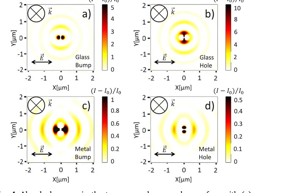
The nature of the defect matters less than one might expect, and in an instructive way. The orientation of the radiative pattern is the same for a hole and for a bump; what changes is the distance between the emission centre and the first maxima, because charge accumulates differently at the interface of a protrusion and of an indentation, which retards the scattered surface wave differently. On glass the pattern is a set of spherical standing waves spaced by the wavelength in the material and oriented perpendicular to the polarization. On metal that symmetry is broken by the plasmon contribution, which adds maxima spaced by about one wavelength in the direction parallel to the field.
There is also a symmetry principle hiding in these maps: superimposing the pattern of a hole and that of a bump of equal size, one is strong where the other is weak. Absorbed-energy maps alone, however, cannot separate the plasmon from the quasi-cylindrical wave, which is exactly why the analytical decomposition above was needed.
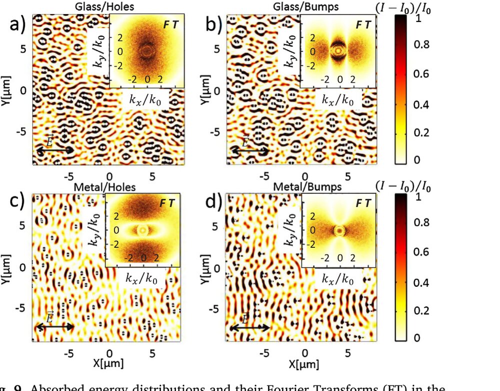
On a statistically rough surface the same two families survive the ensemble average, and they can be read directly in the spectrum of the absorbed energy. Components near or below the wave vector of light come from the radiative, propagating part of the scattered field and give periods above the wavelength in the material. Components extending to several times that wave vector come from the evanescent part and give the finest structures. The two appear in the literature as the type-r and type-s features.
The depth at which the map is computed changes what one sees, because peaks and valleys of the relief do not absorb in the same way. Only the depth-integrated distribution carries both families at once, which is worth remembering when comparing a simulation with a measured topography.
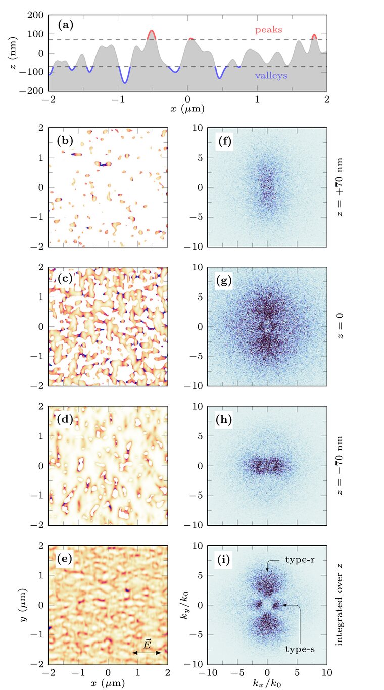
Surface plasmon polaritons are not a prerequisite. Quasi-cylindrical evanescent waves are sufficient, and they require far less restrictive conditions of photoexcitation.
A last, independent argument closes this section. Randomizing the spatial phase of the incident field breaks the ripples into finite domains: periodic order on the surface is, before anything else, a coherence property of the light.
03A statistical surface rather than a drawn one
Modelling one particular bump teaches little about a real sample. The surface is therefore described by a continuous height distribution whose correlation function carries only two parameters, the root-mean-square height and the correlation length, both accessible from a profilometer or an atomic force microscope.
The map that comes out is physical rather than numerical. Deep and narrow inhomogeneities keep light from reaching the bottom of the pits, where it could be scattered in the useful direction, and the polarization-locked spectral features disappear. Broad and shallow ones give a specklelike deposition with no preferred axis. In between lies the window where a well-oriented pattern can grow.

Gaussian correlation function of the surface height. The reference case uses σ = 50 nm and ξ = 100 nm, ten times smaller than the wavelength: a well-polished surface, still able to seed high-frequency structures.
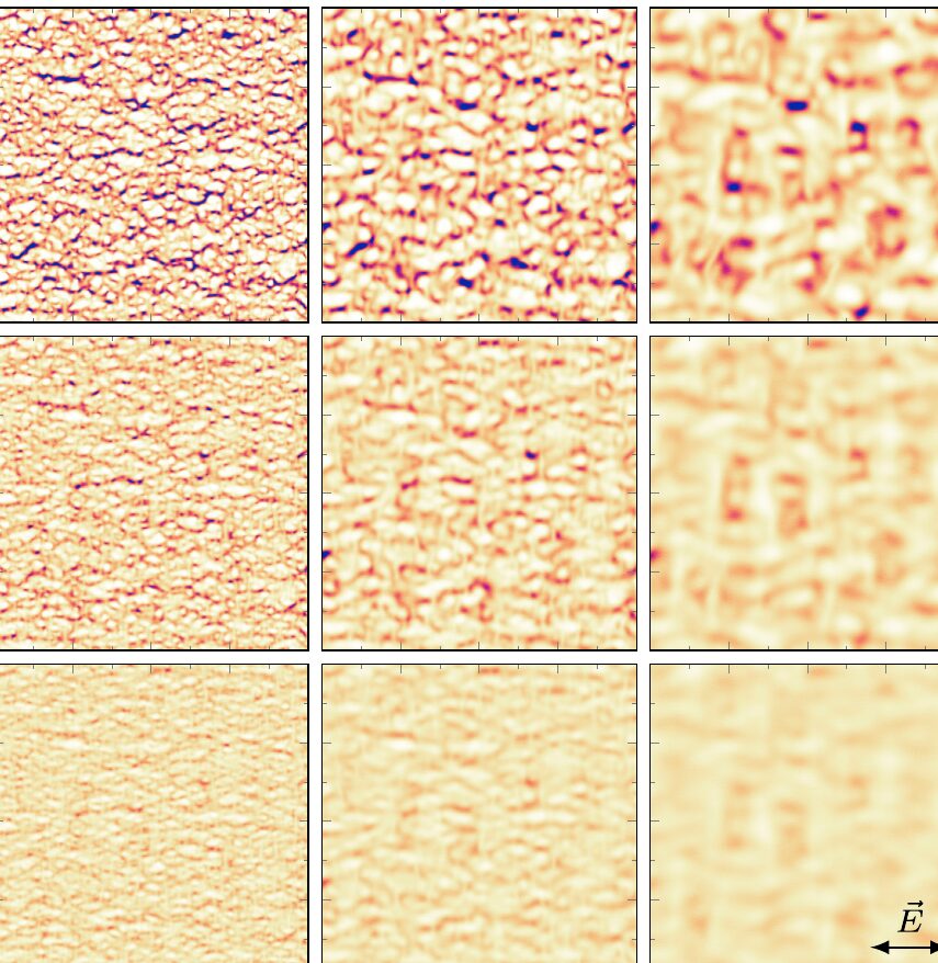
Asymmetry matters more than amplitude. A surface whose correlation length differs along the two in-plane directions, which is what mechanical polishing or a few preceding pulses produce, biases the absorbed energy in a way that circularly polarized pulses detect with remarkable sensitivity. It is also the reason a nominally isotropic sample can develop a well-defined ripple orientation from the very first shots.
04Feedback, angle and polarization state

Incident field before rotation. The ellipticity runs from 0 for linear to 1 for circular polarization, and letting it vary across the beam together with the orientation angle gives radial, azimuthal and arbitrary vector beams.
A single pulse is only the first term of the story. Each pulse rewrites the topography that the next one scatters from, and the surviving pattern is the fixed point of that loop. Including this interpulse feedback reproduces the growth, deepening and phase locking observed in pulse-to-pulse imaging experiments, and it is what turns a broad spectral response into a single selected period.
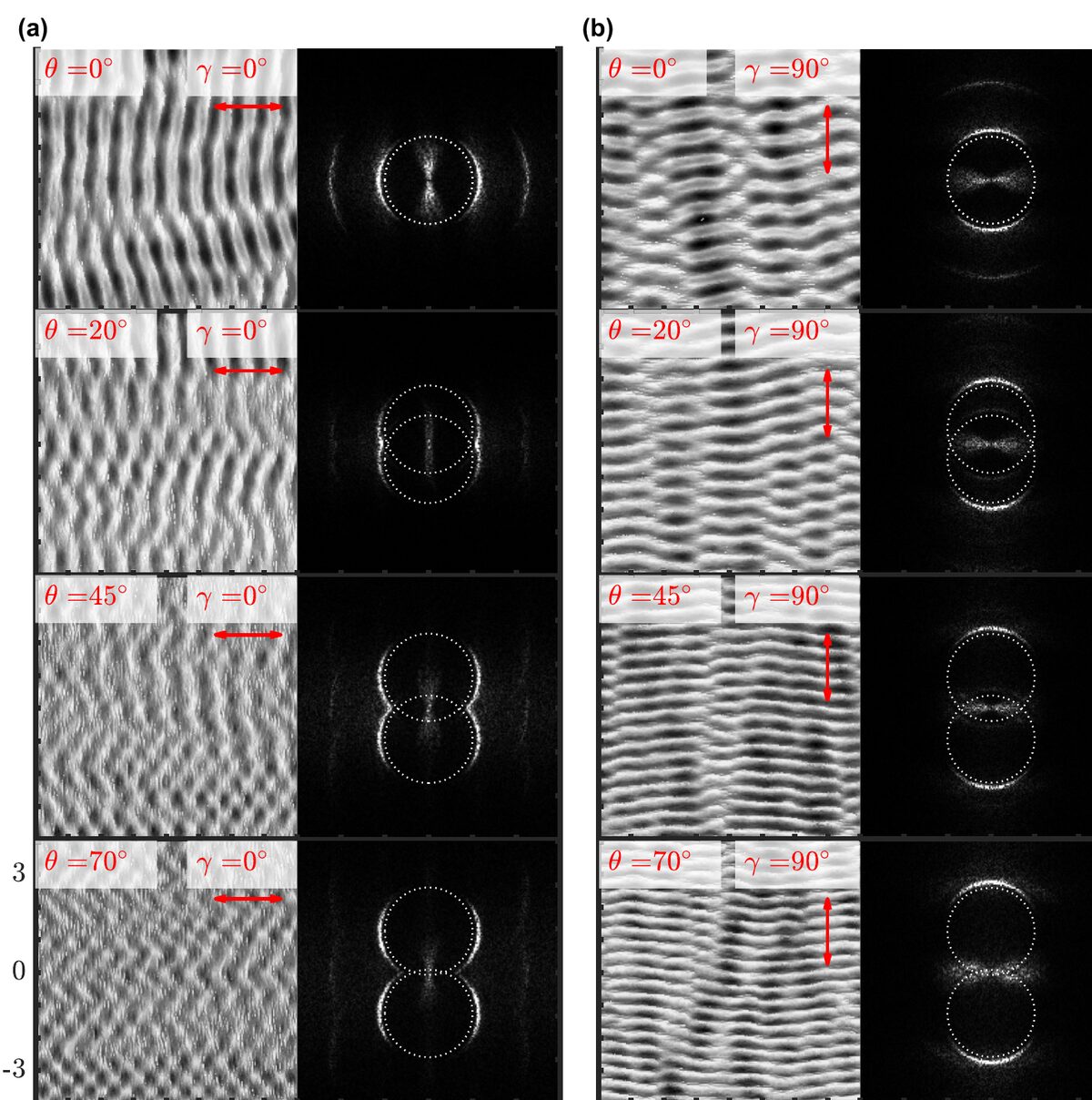
At oblique incidence the in-plane wave vector of the incident light no longer vanishes, and the interference condition involves the angle between it and the wave vector of the scattered light. For s-polarized and mixed beams at large angles the ripples then orient neither perpendicular nor parallel to the polarization, a prediction that a normal-incidence picture simply cannot produce. Circular polarization yields the triangular and fine-dot morphologies reported experimentally, while the high-frequency structures keep almost the same period whatever the incidence and polarization angle, consistent with their evanescent origin.
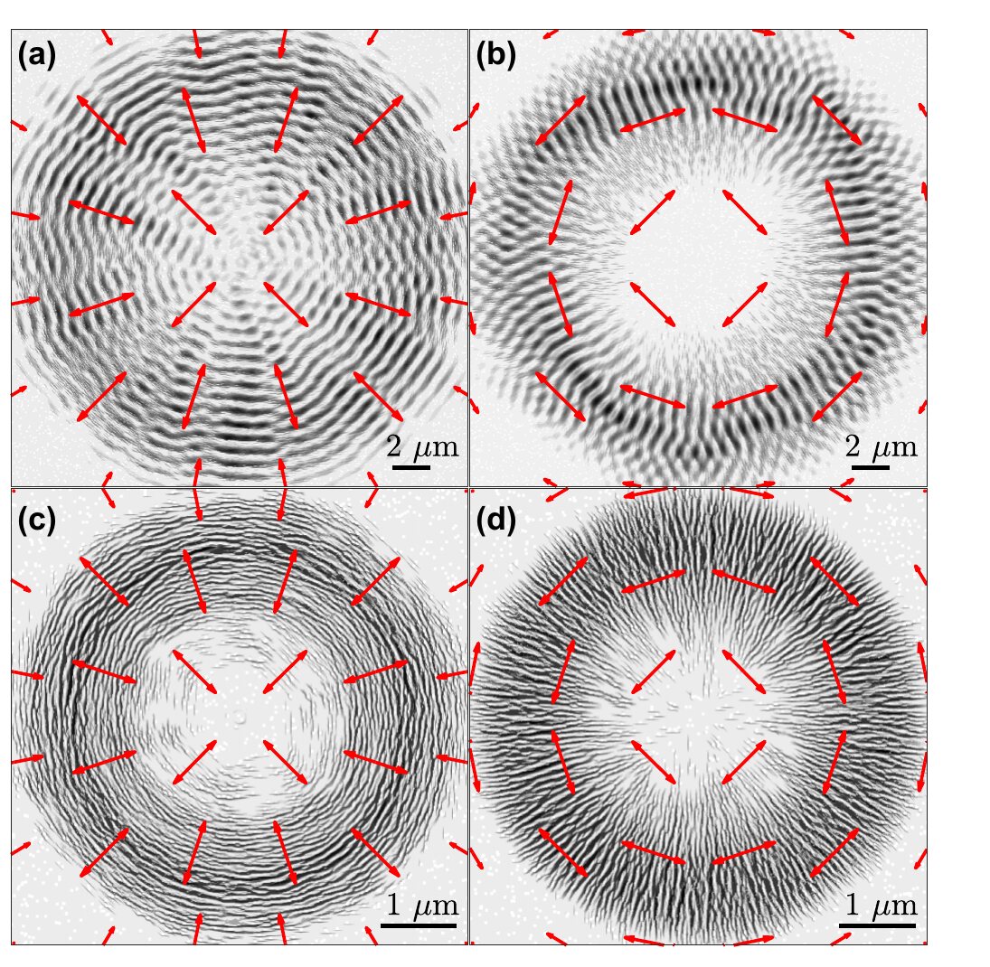
A beam whose polarization is structured in space writes a structured surface, because the local rule is unchanged and only the boundary condition varies. Keep that in mind for what follows, because a beam whose phase is structured is a very different matter: the local rule sees almost nothing of it.
05The same mechanism inside a dielectric
Nanogratings written in the bulk of fused silica and ripples formed on its surface share subwavelength periodicity, the same orientation relative to the polarization, and the same origin: local field enhancement near inhomogeneous scattering centres, with the period set by the coherent superposition of the scattered waves. It also explains why both need pulse accumulation, the excitation having to build up over successive shots before the pattern locks in.
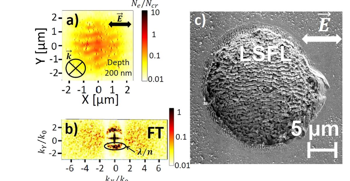
In photoexcited silicon the coupling also runs the other way. A free-carrier density around 3 × 1021 cm-3, measured by time-resolved ellipsometry and supported by time-dependent density functional theory, changes the optical indices enough to reorganize the interference itself. The result is a crossed periodic deposition mixing topography and structural modification, obtained without invoking surface plasmon polaritons.
06Can orbital angular momentum be printed on a surface?
A vortex beam carries a helical wavefront whose phase winds by an integer number of turns around the axis. The expectation is natural, a twisted beam should write a twisted structure, and the stakes go beyond laser processing, towards chiral sensing and enantioselective surface chemistry.
After a systematic exploration of topological charges, polarization states and pre-structured surfaces, the answer is no. Orbital angular momentum leaves the distribution of absorbed energy on a rough surface unchanged, and does not induce chiral ripples.

Phase imposed at the source: a helical wavefront of topological charge ℓ, plus a conical term describing convergence with a half-angle δ.
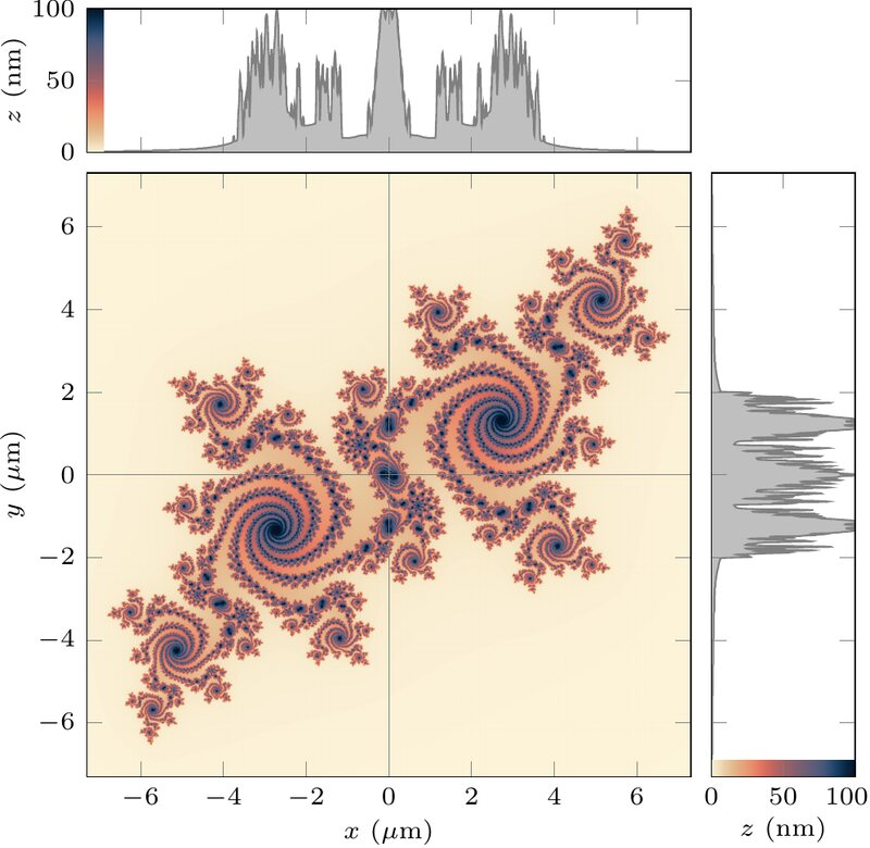
Could a surface that is already chiral respond to the sign of the charge, as individual chiral nanostructures do? Rather than a parametric study over nanoparticle arrays, the flat surface was replaced by a fractal relief: a Julia set protruding 100 nm above the metal, whose self-similar boundary provides chiral elements at every scale from several wavelengths down to subwavelength sizes. A single simulation then scans the whole range, and some of those scales must be in resonance with the incident light.
The verdict is unambiguous. Apart from the dark core produced by the phase singularity, the absorbed energy is the same with and without orbital angular momentum. The spectra do contain more high-frequency components than on a merely rough surface, but only because the fractal offers much smaller scatterers.

The quadratic map whose Julia set defines the relief. Its self-similarity removes the need to guess which feature size would respond.
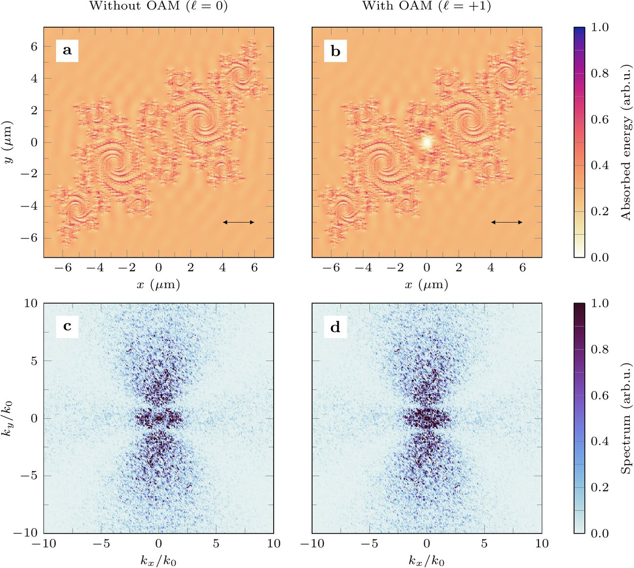
The reason follows from everything above. Local absorption is governed by the polarization and by the near-field scattering geometry, both essentially blind to the slow azimuthal phase ramp of a vortex beam. The handedness lives in the global wavefront, at a scale far larger than the features being written, so the pulse-to-pulse feedback has nothing chiral to amplify.
07Spirals by interference
The indirect route works. Superimposing a focused vortex pulse with a second pulse having a plane wavefront produces a spiral intensity distribution whose number of arms follows the topological charge. The ripples inside each arm remain governed by the local polarization, so the two length scales are decoupled: interference sets the large-scale chiral arrangement, near-field scattering sets the subwavelength period.
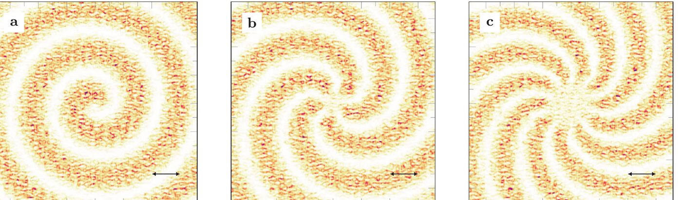
The limitation is honest: the spiral is an interference pattern, so its scale is set by the beams and cannot go below the laser wavelength. To reach a genuinely subwavelength chiral effect the absorbed energy is the wrong observable. The forces are.
08Where the mechanical action comes from
Starting from the Lorentz force on a bound charge distribution, with a polarization density and a current derived from it, the force per unit volume in a linear medium splits into two terms. Only one of them can leave a lasting signature.

Optical force per unit volume. The first term, proportional to the field gradient, pushes matter out of the high-intensity regions and acts parallel to the surface. The second is directed along the Poynting vector, into the material.
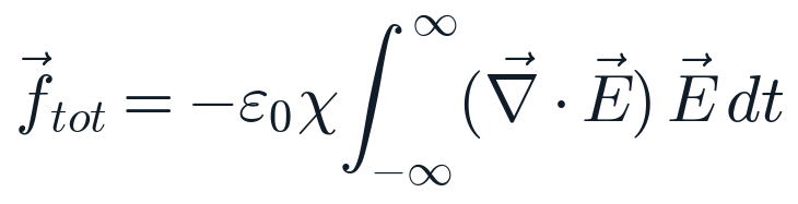
Accumulated force, the quantity still acting on the transient melt once the pulse has gone. This is what has to be non-zero, and vortical, for a beam to twist a surface.
Since the electric and magnetic fields oscillate at the same frequency, the time derivative shifts one of them by a quarter period, making the second term an odd function of time whose integral vanishes. What survives the pulse is entirely due to the gradient term, and it acts in the plane of the surface, where it can displace the transient melt.
09Does a vortex beam twist matter?
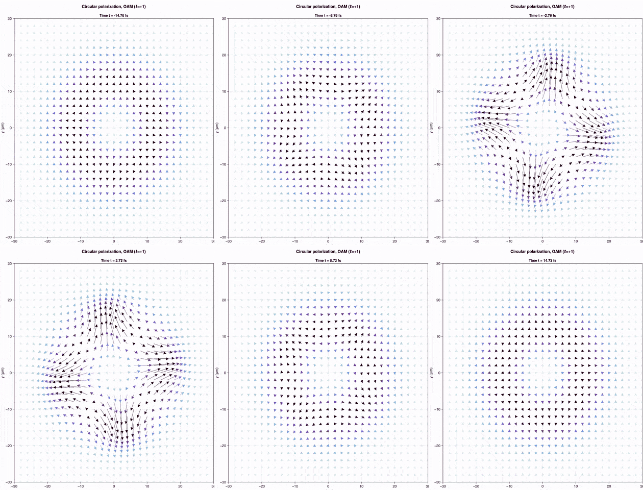
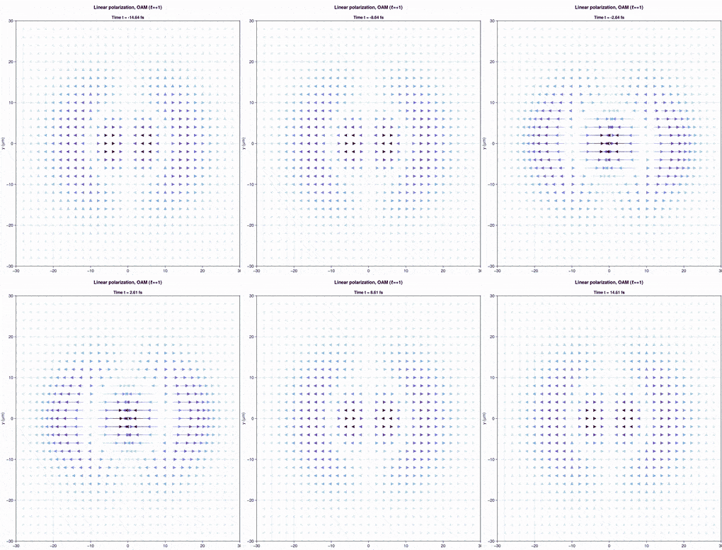
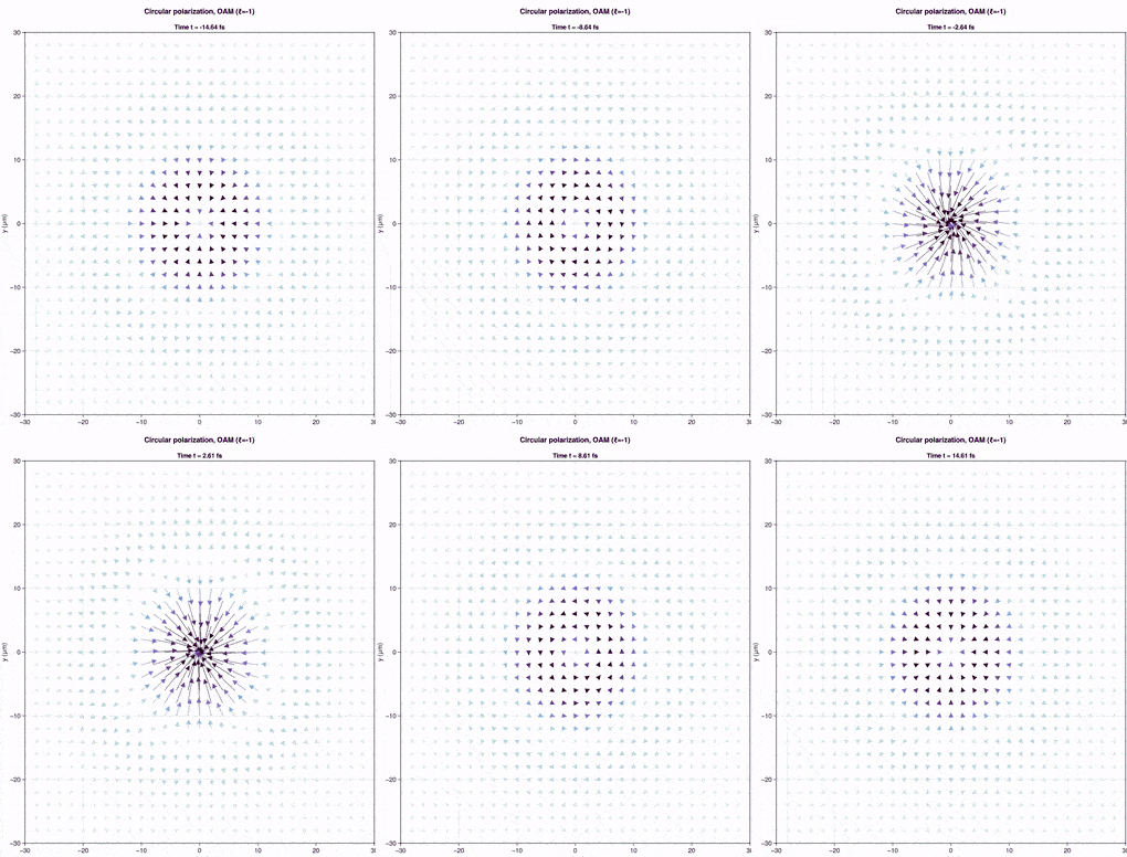
Comparing configurations settles it. With linear polarization the force vectors stay aligned with the polarization while their distribution rotates with the helical wavefront, and that rotation averages out over the pulse. With circular polarization and co-rotating charge the distribution rotates as well, but lacks the components directed toward the beam centre, so the residue is radial. With counter-rotating charge the twisting component oscillates in time and again leaves a purely radial residue.
10The configuration that works
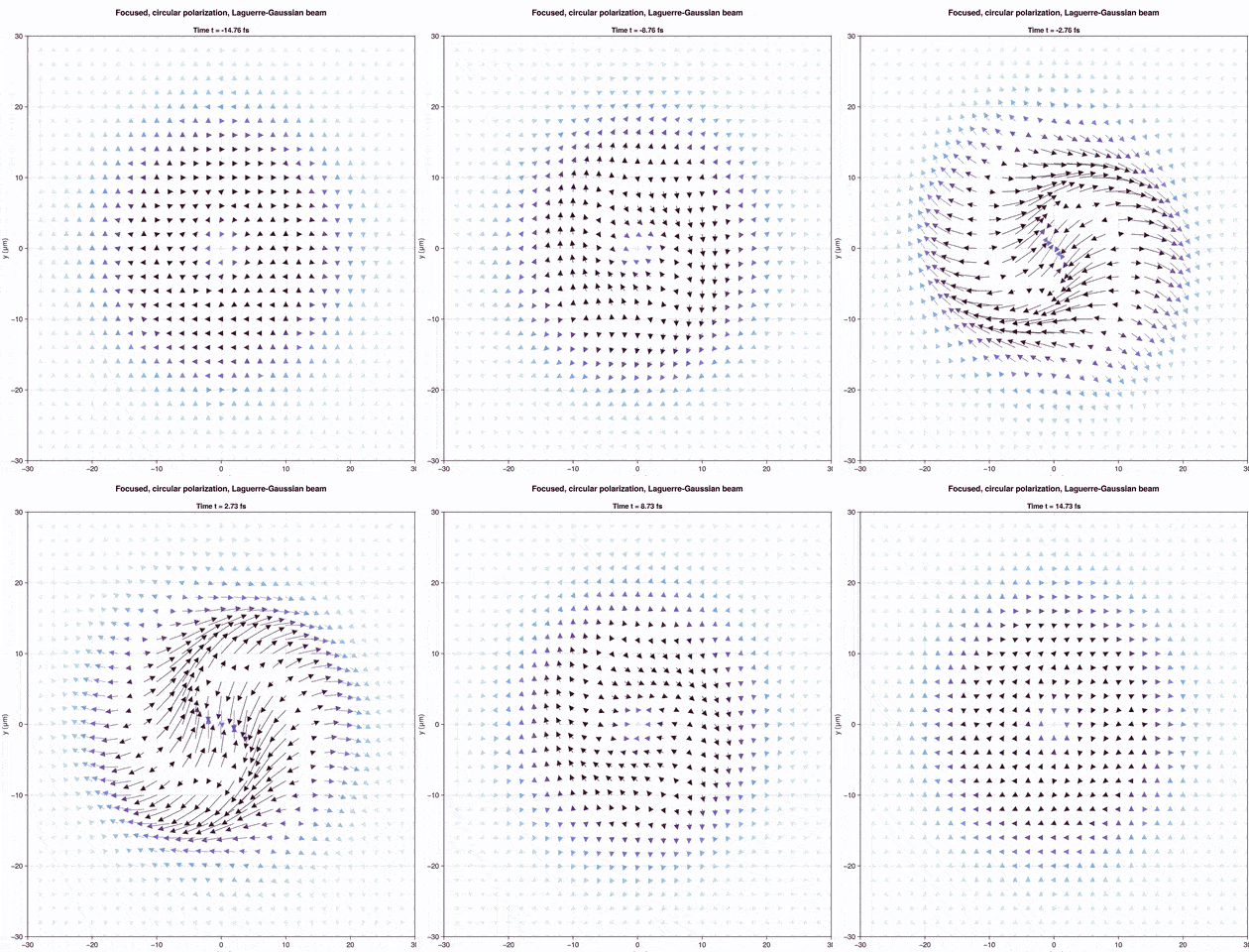
Focusing changes the outcome. A tightly focused circularly polarized pulse, with or without orbital angular momentum, leaves a total force field whose vectors are arranged along a spiral: the vorticity of the instantaneous distributions no longer cancels, it accumulates. The handedness that reaches the surface therefore comes from the spin of the light and from the focusing geometry, not from the orbital angular momentum on its own.
This is consistent with the clockwise and counterclockwise nanopillar arrays reported for left and right-handed circular polarization on zinc oxide, and it identifies the configuration to use when the aim is to apply a torque to the molten layer rather than simply to heat it.
11What this opens
The same toolbox extends to propagation inside transparent solids, where the beam is no longer imposed from outside but reshaped by the material: elliptical non-diffractive beams keep an engineered cross-section over long distances in bulk fused silica while the Kerr response and the generated free carriers deform them, the regime relevant to writing waveguides and volume nanogratings.
Taken together these results draw a usable map. Absorbed energy is governed by the polarization and by the statistics of the surface, through an interference between the incident light and two surface waves of comparable weight. Chirality is reachable, but through interference at the large scale and through optical torque at the small one. That distinction is what makes the design space practical, for biomimetic surface design, chiral sensing and enantiospecific surface chemistry.
Key publications
- Chiral patterning of rough surfaces with vortex laser beams: from structured polarization to twisted forcesV. Yu. Fedorov, J.-P. Colombier, Laser & Photonics Reviews 2401540 (2025). doi.org/10.1002/lpor.202401540
- Light-matter interaction at rough surfaces: a morphological perspective on laser-induced periodic surface structuresV. Yu. Fedorov, J.-P. Colombier, Physical Review B 110, 115438 (2024). doi.org/10.1103/PhysRevB.110.115438
- Nonlinear propagation of ultrafast elliptical non-diffractive beams in bulk fused silica glassV. Fedorov, R. Dwivedi, C. D’Amico, J.-P. Colombier, R. Stoian, Applied Physics Letters 128, 011102 (2026). doi.org/10.1063/5.0292688
- Laser-induced periodic surface structures: arbitrary angles of incidence and polarization statesH. Zhang, J.-P. Colombier, S. Witte, Physical Review B 101, 245430 (2020). doi.org/10.1103/PhysRevB.101.245430
- Mixing periodic topographies and structural patterns on silicon surfaces mediated by ultrafast photoexcited charge carriersJ.-P. Colombier, A. Rudenko, E. Silaeva, H. Zhang, X. Sedao, E. Bévillon, S. Reynaud, C. Maurice, F. Pigeon, F. Garrelie, R. Stoian, Physical Review Research 2, 043080 (2020). doi.org/10.1103/PhysRevResearch.2.043080
- Self-organization of surfaces on the nanoscale by topography-mediated selection of quasi-cylindrical and plasmonic wavesA. Rudenko, C. Mauclair, F. Garrelie, R. Stoian, J.-P. Colombier, Nanophotonics 8, 459 (2019). doi.org/10.1515/nanoph-2018-0206
- Light absorption by surface nanoholes and nanobumpsA. Rudenko, C. Mauclair, F. Garrelie, R. Stoian, J.-P. Colombier, Applied Surface Science 470, 228 (2019). doi.org/10.1016/j.apsusc.2018.11.111
- Spontaneous periodic ordering on the surface and in the bulk of dielectrics irradiated by ultrafast laser: a shared electromagnetic originA. Rudenko, J.-P. Colombier, S. Höhm, A. Rosenfeld, J. Krüger, J. Bonse, T. E. Itina, Scientific Reports 7, 12306 (2017). doi.org/10.1038/s41598-017-12502-4
- Coherence in ultrafast laser-induced periodic surface structuresH. Zhang, J.-P. Colombier, C. Li, N. Faure, G. Cheng, R. Stoian, Physical Review B 92, 174109 (2015). doi.org/10.1103/PhysRevB.92.174109

